|
|
|
| |
|
DENSE PLASMA FOCUS LABORATORY»RESEARCH |
Following studies have been made during last one decade using this PF device:
• Studied the dynamics of current sheath of PF using multiple magnetic probe arrangements.
- Investigated X-ray emission of PF using diode X-ray spectrometer and X-ray pinhole camera.
- Used X-ray emission for the radiography purpose.
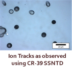
- Observed ion dynamics of PF using single and multiple Faraday cup arrangement and SSNTD.
- Studied the electron beam current of PF using electron collector and Rogowski coil.
- Portrayed PF device as a suitable alternate of nitriding reactor by using it for hardening of steel.
- Succeeded to prepare theoretically predicted material CARBONITRIDE (harder than diamond) on graphite substrate by using nitrogen ions of PF device.
- Used energetic ions of PF for creation of colour centres in American Diamond.
- Used electron beam of PF device to grow NANOWIRE of polyaniline at room temperature.
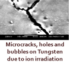
- Studying protons and noble gas ions irradiation on materials that are of interest in tokamak reactor.
|
|
|
|
|
|
| |
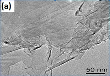
Alpha particles emanated from our PF device were bombarded on electrode grade graphite as well as tungsten samples in order to study the morphological and structural changes occurring on them due to irradiation.
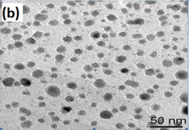
Surface morphological studies of graphite samples have already carried out using HRTEM, FESEM and AFM. The reference samples exhibit layered type of structure where as the irradiated samples exhibit rounded structure as shown in TEM micrographs (Fig. I).
|
|
|
Fig. I: TEM micrographs of (a) references, (b) ion irradiated samples |
| |
|
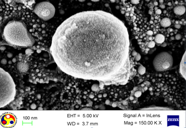
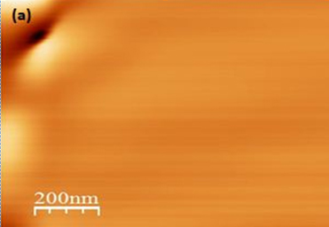
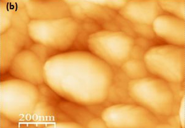
FESEM micrograph illustrates clusters of carbon nanodots in the shape magnificent spheroid (Fig. II ). These nanodots are of the dimension of 10 nm. Surface topography of irradiated sample under AFM further substantiates the spheroid structures as shown in Fig. IIIa whereas reference sample depicts smooth surface (Fig. IIIb).
|
|
Fig.II: FESEM micrographs depcting ensamble of nanodots |
| |
|
|
|
Fig.III: AFM micrograph of (a) reference, (b) ion irradiated sample |
|
|
|
| |
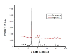 |
XRD pattern of exposed graphite indicates that many new planes have been developed (unmarked peaks) as shown in Fig. IV. SAED pattern of the exposed sample is also indicative of development of new planes due to the thermal load deposited onto the sample. |
Fig. IV: XRD pattern of reference and ion irradiated samples |
|
|
| |
|
|
|
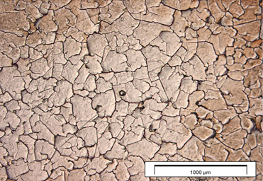
Fig.V: OM micrograph of ion irradiated sample |
|
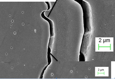
Fig.VIa: FESEM micrograph of ion irradiated sample indicating crystal defects |
| |
|
|
|
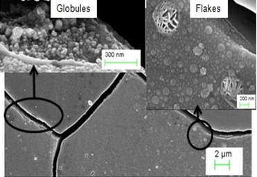
Fig.VIb: FESEM micrograph of ion irradiated sample showing nano-globules and flakes |
|
| |
|
| |
• |
Studies on Dense Plasma Focus”, a BRNS, DAE, India project 1997-1999 |
• |
Experimental Studies of X-ray and ion emission form CPP Plasma Focus facility”, a BRNS, DAE India project 1999-2002. |
• |
Studies on hydrogen and noble gas ion implantation on materials of interest in tokamak reactor” CPP-IPR collaboration project 2007-2010. |
|
| |
|