Overview of the laboratory
Portable and cheap neutron sources are on demand for various applications such as in oil and gold mining, cancer therapy, fusion material study,
non-invasive interrogation of illicit drugs and explosive materials, identification of impurities in coal etc. Among the various available neutron sources,
inertial electrostatic confinement fusion (IECF) is an extremely compact and simple device that produces high flux of neutrons. Many laboratories in US and
Japan are doing extensive R & D to bring out an economic and compact IECF neutron source for diverse practical utilities.
|
|
|
|
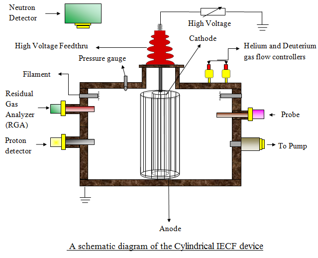
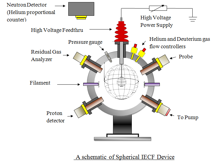
Figure 1: Schematics of cylindrical and spherical IECF chamber
|
In India, the first ever IECF based neutron source has been developed at CPP-IPR. The objective of the program is to develop portable/handheld neutron
sources having linear and spherical geometry which will operate under continuous and repetitive burst mode and produce neutrons at the rate of 100 million
to 10 billion per second. Such high flux neutron source is expected to provide the scope not only to examine the damage occurring in electronic components
and fusion materials but also for the societal benefits.
Inertial Electrostatic Confinement (IEC) is a fusion concept in which fuel ions are trapped with purely electrostatic fields in a convergent geometry
(spherical or cylindrical). The device based on this concept is relatively smaller in size and simpler in designing and thus makes it more appealing
compared to other fusion devices. The IECF runs by the electrical discharges in D-D/D-T/D- 3He fuel gas. It basically consists of a nearly transparent
hollow cathode of spherical or cylindrical geometry housed inside a vacuum chamber (figure 1) filled with the fuel gas. Sometimes separate concentric
anode of respective geometry is kept at ground potential. Initially a glow discharge is initiated to ionize the background gas medium by making filamentary
discharge. The deuterium ions, subject to large electrostatic field of the order of few tens of kV, are then accelerated towards the negatively charged
inner cathode grid and subsequently create the fusion reaction.
|
|
|
|
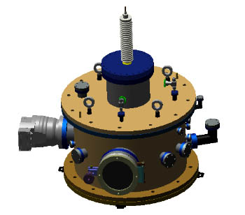
Figure 2: Artistic view of the cylindrical IECF device
|
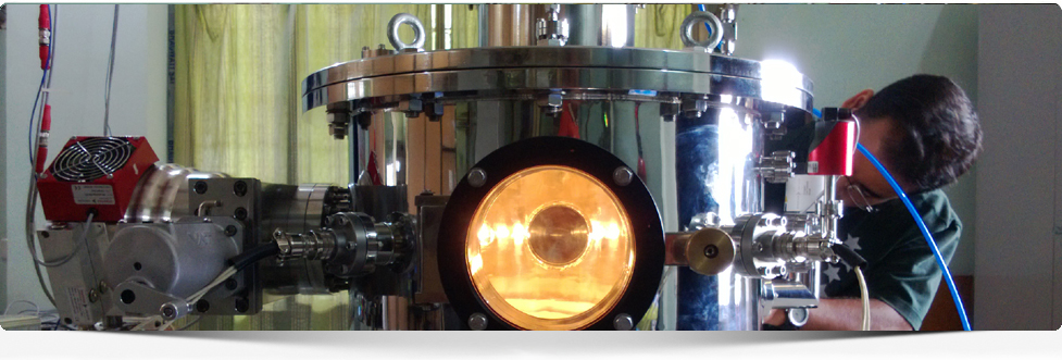
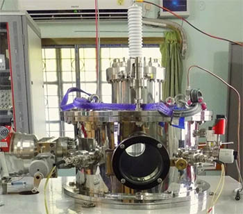
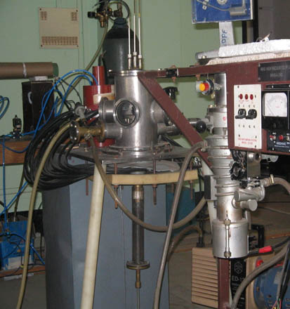
Figure 3: A snap of the cylindrical IECF device
|
Experimental Setup of the cylindrical IECF device
3D drawing and the experimental setup of the cylindrical IECF device that is developed at CPP-IPR are shown in figure 2 and figure 3, respectively.
It basically consists of a cylindrical tungsten cathode grid kept inside a cylindrical stainless steel chamber of 50 cm in diameter and 30 cm in height
placed vertically. The chamber has multiple ports for evacuation, viewing windows, high voltage feedthrough, gas inlets and coupling different diagnostics.
Top port of the chamber is used as an access port for high voltage feedthrough and one side port is dedicated for coupling to the evacuation system.
The cathode grid is made up of tungsten with varying dimension and transparency. The chamber was evacuated using a turbo molecular pump and the working
gas pressure of deuterium was maintained in the chamber by using a coarse feed valve.
Experimental Setup of the spherical IECF device
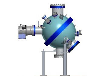
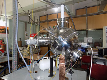
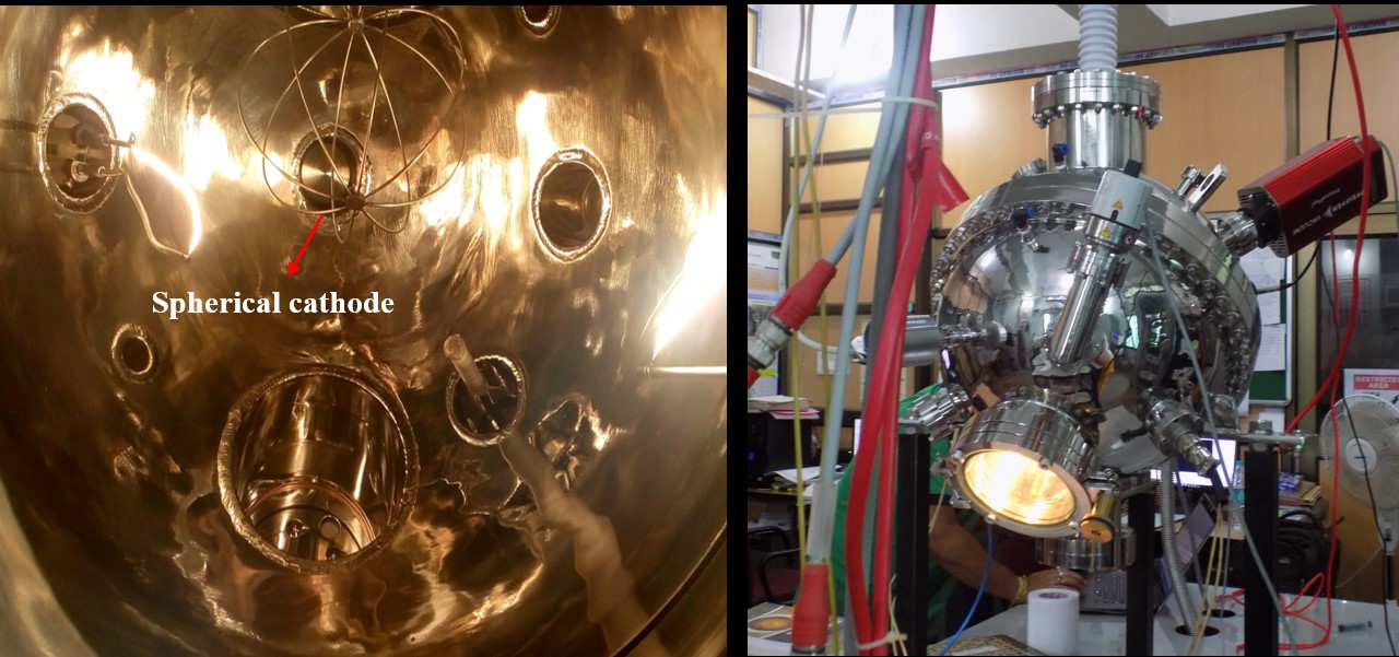
3D drawing and the experimental setup of the spherical IECF device are shown in figure 4 and figure 5, respectively. It basically consists of a stainless
steel cathode grid kept inside a spherical stainless steel chamber of 50 cm in diameter. The chamber has multiple ports for evacuation, viewing windows,
high voltage feedthrough, gas inlets and coupling different diagnostics. The accessories mainly coupled to the spherical vacuum chamber are turbo molecular
pump backed by rotary pump, cold cathode gauge, filament feedthrus, H.V DC feedthrough, spherical cathode grid as shown in figure 5.
|
|
|
|
Figure 4: Artistic view of the spherical IECF device
|
Figure 5: Photograph spherical IECF device
|
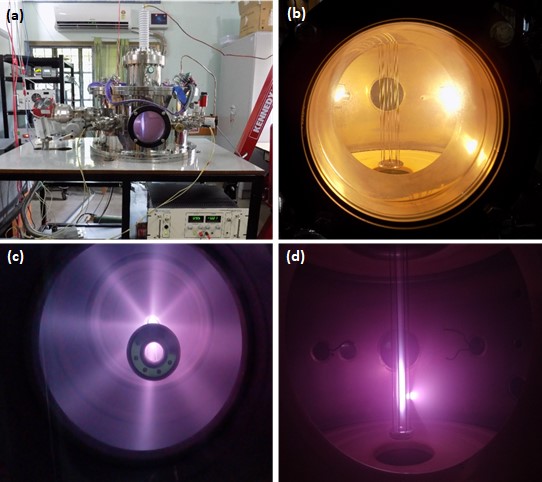
Production and characterization of discharge plasma in the cylindrical IECF Device
The deuterium plasma has been produced inside the IECF device so as to ascertain the optimum conditions such as density, and temperature required for enhancing
the neutron production rate from the source (cylindrical IECF device). The discharge techniques employed to create plasma are the hot and the cold cathode
discharges. In the hot cathode discharge, the thermionic electrons emitted from the filaments ionize the neutral gas and initiates the plasma inside the
chamber. On the other hand, in the cold cathode discharge, the plasma is created on application of high electric field between the cathode grid and the
chamber. The gas breakdown results in a self-sustaining discharge that is adjusted by increasing ionizations with the background gas and secondary electron
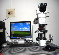
emission from the cathode grid. Diagnostic tools namely Langmuir probe and the Optical Emission Spectroscopy (OES) are employed to characterize the plasma.
The snaps of the hot and cold plasma discharge are shown in figure below. The snap (c) indicates “star mode” of operation whereas snap (d)
illustrates “jet mode”.
|
|
The discharge plasma inside the cylindrical IECF device
|
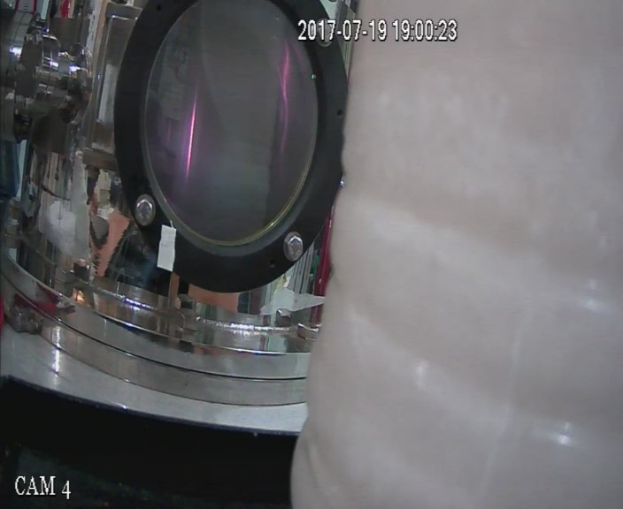
Emission of DD fusion neutrons from the cylindrical IECF device
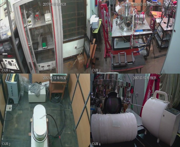
The experiment has been conducted for realizing the emission of 2.45 MeV D-D fusion neutrons from the cylindrical IECF device during continuous mode of
operation. The parameters that control the production of neutrons in this device are the working pressure of the fuel gas, applied voltage, measured
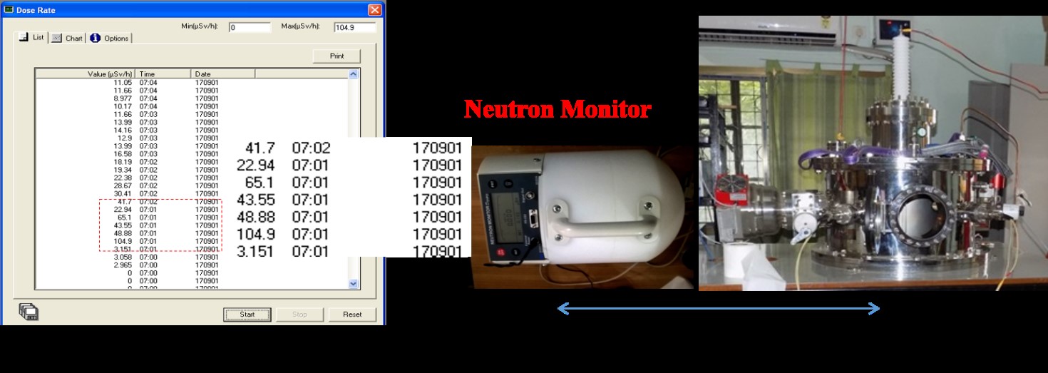
current, cathode geometries and its transparencies. The neutrons emitted from the source are detected using neutron monitor, bubble dosimeters, nuclear
track detectors and He-3 proportional counter. The device currently produces neutrons up to the order of ~ $10^6$ n/sec at discharge voltage ranging from -60 kV
to -80 kV and discharge current of 20 mA to 30 mA. The snaps of the system captured during high voltage operation are shown in figure 1 below.
|
|
|
|
Figure 1: Schematics of cylindrical and spherical IECF chamber
|
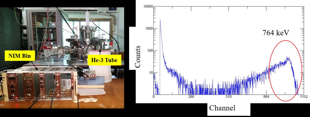
The signatures of the emission of neutrons from the IECF device are obtained by using the above mentioned detectors. The dose rate and the energy are
obtained using the neutron area monitor and the He-3 proportional counter shown below in figure 2 and 3, respectively.
|
|
Figure 2. The dose rate of neutrons obtained during -60 kV, 10mA operation
|
|
|
Figure 3. Signature of the neutron energy peak in the specific channel of the He-3 counter
|
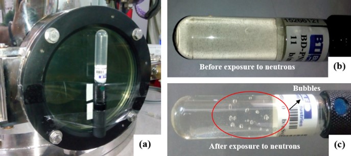
We have also used some non-electronics detectors such as bubble detector (figure 4) and CR-39 (figure 5) to sense neutron emission from the cylindrical
IECF device. The bubble detector was fixed to one of the windows of IEC device as shown in figure 4 (a). We found the development of bubbles in the
detector as a result of incident neutrons in contact with the liquid droplets of the detector. The photograph shown in figure 4 (b) clearly shows the
appearance of the detectors before and after neutron exposure. As per the calibration reports of the detector using a known Am-Be source 1 bubble is
equivalent to 1 μSv of radiation dose. In our case when we exposed the dosimeter at -60 kV, 10 mA, the number of bubbles appeared was 8, and as soon as
we increased the measured current to 30 mA, the number increased to 13, i.e. recording the dose rate to 13 μSv. Thus, we have successfully reported in
recording the neutron dose from our cylindrical IECF source using bubble detectors.
|
|
Figure 4. Photograph of bubble detector (b) before and (c) after exposure to neutrons
|
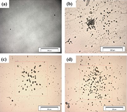
The DD neutrons scatter elastically in CR-39 plate and produce recoil protons or carbon or oxygen nuclei in it while interacting. However, all detected tracks are indeed due to protons as
the scattered carbon and oxygen ions have a short range in CR-39 due to their higher masses. Figure 5 (a) shows the reference sample, i.e. the unexposed but etched (6 hours) CR 39 plate and
figure 5 (b) shows the plate exposed to neutrons (~ $10^6$ n/s) and etched in NaOH solution up to 6 hours. The tracks formed in the plate are visible and shows some dark, round and oval tracks.
The oval-shaped track is expected due to oblique incidence of neutrons. On increasing the current levels 10 mA and 30 mA, working pressures 0.9 mTorr and 0.7 mTorr while keeping the voltage
fixed at -60 kV the number of tracks increased (figure 5 (c) and 5 (d)) and revealed the increase in neutron flux from the cylindrical source.
|
|
Figure 5. Photograph of proton recoil tracks of neutrons as observed in CR-39: (a) before exposure and (b)-(d) after exposure to neutrons
|
Application of the IECF device for explosive detection
The IECF device has the advantages of its portability and robustness in the production of neutrons and, therefore, the device can provide versatile
applications, including anti-personnel landmine detection. It can also behave as an ideal small accelerator driven fusion neutron source for homeland
security, from the viewpoint of both safety and long lifetime, compared with conventional neutron emitters, such as radioactive isotopes 252Cf, and
a D-T tube.
|
|
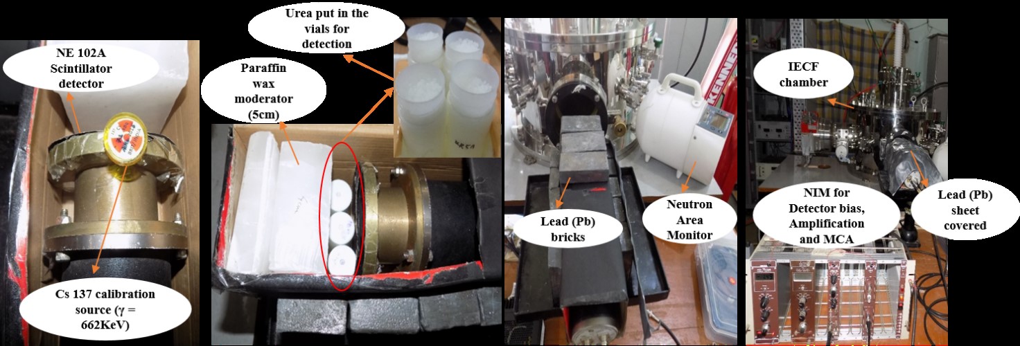
Figure 1. Experimental arrangement for detection of explosive contents in materials
|
The 2.45 MeV neutrons that were being produced from the cylindrical IECF device were utilized for the detection of explosive materials. Neutrons has the
inherent property of activation in materials and this activated nuclei of the materials produces characteristic gamma rays in their decay process. The
explosive materials that are used to prepare bombs, landmines etc. constitutes carbon (C), hydrogen (H), nitrogen (N) and oxygen (O). So, if a neutron
interacts with any of such nuclei it would activate the nuclei and while decaying produce gamma rays (γ). The prime objective of this proof-of-principle
experiment is to detect the emissions from the of Urea nitrate ((NH2)2COHNO3) which is the equivalent to that of Ammonium
nitrate (H4N2O3).
Ammonium nitrate is an explosive that is present primarily in landmines and other explosive sources. The 2.45 MeV from the source are first thermalized
to 0.025 eV using moderators and when these thermal neutrons (0.025 eV) interact with the bag contents, characteristic γ rays are given off. The γ rays of
interest are 10.83 MeV and 2.223 MeV lines from nitrogen and hydrogen respectively. The experimental arrangement and detection of the gamma are presented in
figure 1 and 2 respectively.
|
|
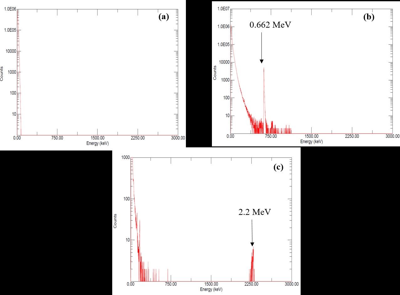
Figure 2. (a) Backgrounds counts of the scintillator, (b) Calibrated counts of gamma using CS-137, (c) Gamma rays of 2.2 MeV due to thermal neutron capture
|
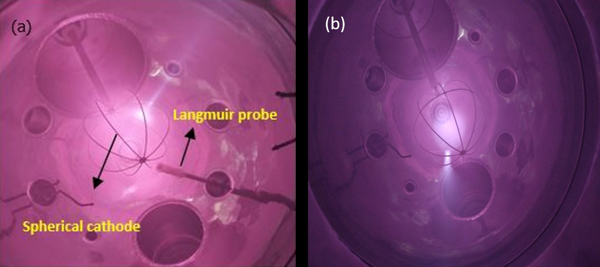
Production of discharge plasma in the spherical IECF device
After the successful installation of the spherical IECF device along with its accessories such as vacuum pumps, pressure gauges, filaments, spherical
cathodes, feedthrough etc. we started to produce plasma discharges inside the spherical device. The hydrogen and deuterium plasma has been produced by
making hot cathode and cold cathode discharges in the chamber that has been shown in figure 1 and 2, respectively. In order to characterize the produced
plasma we employed the planar Langmuir probe that has been interfaced with the source measurement unit (SMU).
|
|
Figure 1. Hot cathode discharge plasma inside the spherical IECF device
|
|
|
Figure 2. Cold cathode discharge plasma inside the spherical IECF device
|
Design and development of the pulsed power driver
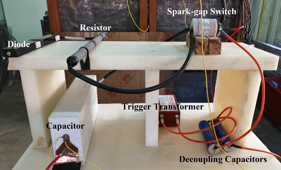
We have designed a pulsed power driver using 0.04 µF, 100kV NWL capacitor and Z/3T/100 Zeonics make High Voltage Spark Gap Switch to drive the IECF device
in pulse mode of operation. The spark has SBV (Self Breakdown Voltage) of ±100kV to ±120kV DC. To trigger the spark gap a trigger pulse ±40kV was generated
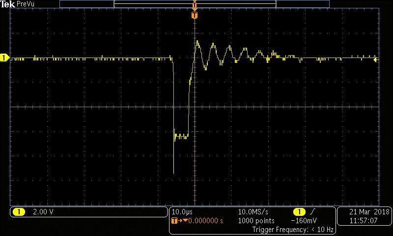
using a pulse generator and a trigger transformer. The complete circuit arrangement of the pulse power driver is shown in the figure 1. Figure 2 shows the
pulsed output observed in the oscilloscope when - 60 kV DC input is applied and the experimental output of - 60kV, 5µs pulse.
|
|
Figure 1. Setup of the pulse power driver unit
|
|
|
Figure 2. Output pulse observed after operating the pulse power driver
|
Application of IECF device in X-ray radiography
Apart from the neutron, X-ray is another important product of the device. Both hard and soft X-rays can be produced from the device keeping the configuration of the device same as that for the
neutron study. Recently, study on hard X-ray has been performed using the cylindrical IECF device as the source and these X-rays are used in radiography of some high density materials.
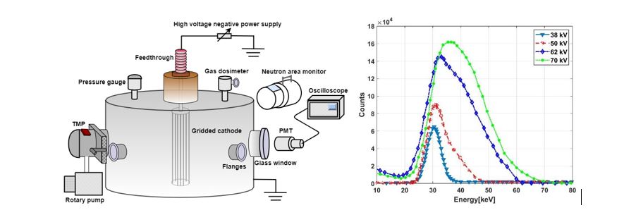
The X-rays have been detected by using a PMT and the X-ray energy spectra is obtained in the PC interface. The continuous broad energy spectra (fig. 1) suggest the generation of Bremsstrahlung
radiation due to the interaction of the accelerating electrons with the anode wall and also with the Coulomb field of ions inside the cathode.
|
|
Figure 1. Schematic of the device for X-ray detection (left), obtained X-ray energy spectra (right).
|
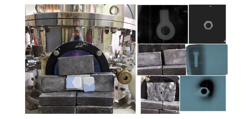
For X-ray radiography, dental X-ray photographic films have been used and the samples are attached to the film so that the X-ray passed through the sample before reaching the film. Some of the
obtained radiography images of some metallic samples are shown in fig. 2.
|
|
Figure 2. Photograph of the X-ray film in front of the device’s window during experiment (left), Some of the radiography images of metallic sample (right).
|
|